Two neighboring switches can treat multiple parallel links between each other as a single logical link called an Ether Channel. Without Ether Channel, a switch treats each physical port as an independent port, applying MAC learning, forwarding, and STP logic per physical port. With Ether Channel, the switch applies all those same processes to a group of physical ports as one entity: the Ether Channel. Without Ether Channel, with parallel links between two switches, STP/RSTP would block all links except one, but with Ether Channel, the switch can use all the links, load balancing the traffic over the links.
Ether Channel may be one of the most challenging switch features to make work. First, the configuration has several options, so you have to remember the details of which options work together. Second, the switches also require a variety of other interface settings to match among all the links in the channel, so you have to know those settings as well.
Configuring a Manual Layer 2 Ether Channel
To configure a Layer 2 Ether Channel so that all the ports always attempt to be part of the channel, simply add the correct channel-group configuration command to each physical interface, on each switch, all with the on keyword, and all with the same number. The on keyword tells the switches to place a physical interface into an Ether Channel, and the number identifies the Port Channel interface number that the interface should be a part of.
Before getting into the configuration and verification, however, you need to start using three terms as synonyms: Ether Channel, PortChannel, and Channel-group. Oddly, IOS uses the channel-group configuration command, but then to display its status, IOS uses the show etherchannel command. Then the output of this show command refers to neither an “EtherChannel” nor a “Channel-group,” instead using the term “PortChannel.” So, pay close attention to these three terms in the example.
To configure an EtherChannel manually, follow these steps:
Step 1. Add the channel-group number mode on command in interface configuration mode under each physical interface that should be in the channel to add it to the channel.
Step 2. Use the same number for all commands on the same switch, but the channelgroup number on the neighboring switch can differ.
Below shows a simple example, with two links between switches SW1 and SW2. The configuration shows SW1’s two interfaces placed into channelgroup 1, with two show commands to follow.

SW1# configure terminal
SW1(config)# interface fa 0/14
SW1(config-if)# channel-group 1 mode on
SW1(config)# interface fa 0/15
SW1(config-if)# channel-group 1 mode on
SW1(config-if)# ^Z

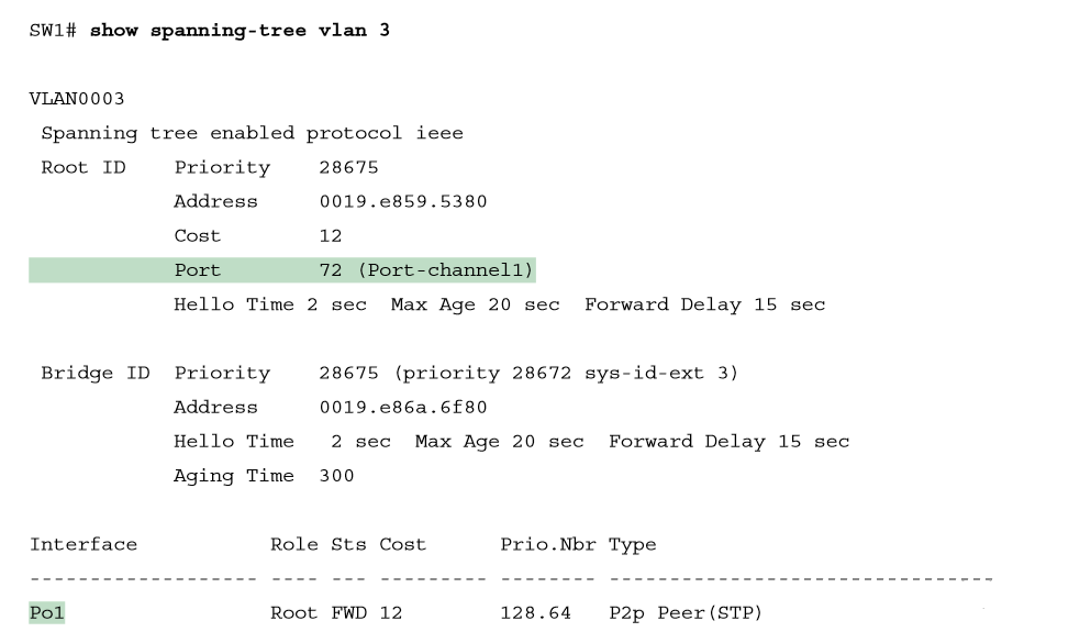
Take a few moments to look at the output in the two show commands in the example, as well. First, the show spanning-tree command lists Po1, short for PortChannel1, as an interface. This interface exists because of the channel-group commands using the 1 parameter. STP no longer operates on physical interfaces Fa0/14 and Fa0/15, instead operating on the Port Channel1 interface, so only that interface is listed in the output. Next, note the output of the show etherchannel 1 summary command. It lists as a heading “Port-channel,” with Po1 below it. It also lists both Fa0/14 and Fa0/15 in the list of ports, with a (P) beside each. Per the legend, the P means that the ports are bundled in the port channel, which is a code that means these ports have passed all the configuration checks and are valid to be included in the channel.
Configuring Dynamic EtherChannels
In addition to manual configuration, Cisco switches also support two different configuration options that then use a dynamic protocol to negotiate whether a particular link becomes part of an Ether Channel or not. Basically, the configuration enables a protocol for a particular channel-group number. At that point, the switch can use the protocol to send messages to/from the neighboring switch and discover whether their configuration settings pass all checks. If a given physical link passes, the link is added to the EtherChannel and used; if not, it is placed in a down state, and not used, until the configuration inconsistency can be resolved.
Most Cisco Catalyst switches support the Cisco-proprietary Port Aggregation Protocol (PAgP) and the IEEE standard Link Aggregation Control Protocol (LACP), based on IEEE standard 802.3ad. Although differences exist between the two, to the depth discussed here, they both accomplish the same task: negotiate so that only links that pass the configuration checks are actually used in an Ether Channel.
One difference of note is that LACP does support more links in a channel—16—as compared to PaGP’s maximum of 8. With LACP, only 8 can be active at one time, with the others waiting to be used should any of the other links fail.
To configure either protocol, a switch uses the channel-group configuration commands on each switch, but with a keyword that either means “use this protocol and begin negotiations” or “use this protocol and wait for the other switch to begin negotiations.” As shown in Figure, the desirable and auto keywords enable PAgP, and the active and passive keywords enable LACP. With these options, at least one side has to begin the negotiations. In other words, with PAgP, at least one of the two sides must use desirable, and with LACP, at least one of the two sides must use active.

Do not use the on parameter on one end, and either auto or desirable (or for LACP, active or passive) on the neighboring switch. The on option uses neither PAgP nor LACP, so a configuration that uses on, with PAgP or LACP options on the other end, would prevent the EtherChannel from working. Below shows the verification of that configuration, with the command show etherchannel 1 port-channel. This command confirms the protocol in use (PAgP, because the desirable keyword was configured), and the list of interfaces in the channel.
SW# show EtherChannel 1 port-channel
You can verify protocol and interface from output.


