Let’s dive into how to configure STP on switch. We will also look into how STP topology change occurs, what happens when link failure happens and how to protect STP.
STP Topology Changes
An STP topology change will occur under two circumstances:
- When an interface is placed into a Forwarding state.
- When an interface already in a Forwarding or Learning state is placed into a Blocking state.
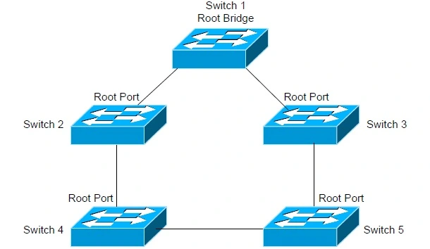
The switch recognizing this topology change will send out a TCN (Topology Change Notification) BPDU, destined for the Root Bridge. The TCN BPDU does not contain any data about the actual change – it only indicates that a change occurred. For example, if the interface on Switch 4 connecting to Switch 5 went down, Switch 4 would send a TCN out its Root Port to Switch 2. Switch 2 will acknowledge this TCN by sending a BPDU back to Switch 4 with the Topology Change Acknowledgement (TCA) bit set. Switch 2 would then forward the TCN out its Root Port to Switch 1 (the Root Bridge). Once the Root Bridge receives the TCN, it will send out a BPDU with the Topology Change (TC) bit set to all switches. When a switch receives this Root BPDU, it will temporarily lower its MAC-address Aging Timer from 300 seconds to 15 seconds, so that any erroneous MAC addresses can be quickly flushed out of the CAM table. The MAC-Address Aging Timer will stay lowered to 15 seconds for a period of 35 seconds by default, or one Max Age (20 seconds) plus one Forward Delay (15 seconds) timer.

Basic STP Configuration
To enable STP for a specific VLAN:Switch(config)#spanning-tree vlan 10
To disable STP for a specific VLAN:Switch(config)# no spanning-tree vlan 10
To adjust the Bridge Priority of a switch from its default of 32,768, to increase its chances of being elected Root Bridge of a VLAN:Switch(config)# spanning-tree vlan 10 priority 150
To change an interface’s Path Cost from its defaults:Switch(config)# int fa0/24
Switch(config-if)# spanning-tree cost 42
To force a switch to become the Root Bridge:Switch(config)# spanning-tree vlan 10 root primary
The root primary parameter in the above command automatically lowers the switch’s priority to 24,576. If another switch on the network has a lower priority than 24,576, the above command will lower the priority by 4096 less than the priority of the other switch. It is possible to assign a Secondary Root Bridge for redundancy. To force a switch to become a Secondary Root Bridge:Switch(config)# spanning-tree vlan 10 root secondary
The root secondary parameter in the above command automatically lowers the switch’s priority to 28,672. To specify the diameter of the switching topology:Switch(config)# spanning-tree vlan 10 root primary diameter 7
The diameter parameter in the preceding command indicates the length of the STP topology (number of switches). The maximum (and default) value for the diameter is 7. Note that the switching topology can contain more than seven switches; however, each branch of the switching tree can only extend seven switches deep, from the Root Bridge.
STP Link Failure
1. Direct Link failure
When main path goes down and backup path is available for that particular destination from source, is called Direct Link Failure. When the main link goes down then next link takes time to be active. So to make backup path immediately active Uplink fast is used in trunk port.switch# spanning-tree uplinkfast

2. Indirect Link Failure
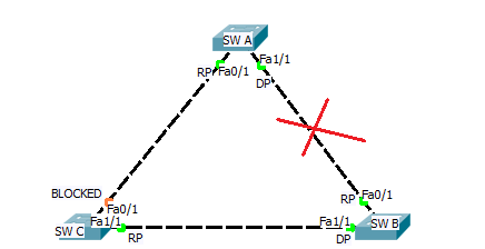
When link between A and B is failed then B says to C that i am Root Brodge and sends BPDU & switch sees that and checks Bridge ID of Switch A and BPDU and sends bridge of of A to B and switc B knows there is a lower bridge in topology. SW C waits for 20 sec before deciding which is max age timer and after 20 sec it start converge the topology. for whole process it takes 52 sec but we can save max age time i.e. 20 sec by using backbone fast command.switch# spanning-tree backbone-fast

STP Protection
STP is vulnerable to attack for two reasons:
- STP builds its topology information by accepting a neighboring switch’s BPDU’s.
- The Root Bridge is always determined by the lowest Bridge ID.
Switches with a low priority can be maliciously placed on the network, and elected the Root Bridge. This may result in a suboptimal or unstable STP topology. Cisco implemented three mechanisms to protect the STP topology:
- Root Guard
- BPDU Guard
- BPDU Filtering
All three mechanisms are configured on an individual interface basis, and are disabled by default. When enabled, these mechanisms apply to all VLANs for that particular interface.
1. Root Guard :
Root Guard prevents an unauthorized switch from advertising itself as a Root Bridge.Switch(config)# interface fa0/10
Switch(config-if)# spanning-tree guard root
The above command will prevents the switch from accepting a new Root Bridge off of the fa0/10 interface. If a Root Bridge advertises itself to this port, the port will enter a root-inconsistent state.
2. BPDU Guard :
BPDU Guard is employed on interfaces that are PortFast-enabled. NOrmally a PortFast-enabled interface connects to a host device, and thus the interface should never receive a BPDU. If another switch is accidentally or maliciously connected into a PortFast interface, BPDU Guard will place the interface into an errdisable state. To enable BPDU Guard:Switch(config)# interface fa0/10
Switch(config-if)# spanning-tree bpduguard enable
To take an interface out of an errdisable state, simply disable and re-enable the interface:Switch(config)# interface fa0/10
Switch(config-if)# shutdown
Switch(config-if)# no shutdown
3. BPDU Filter :
BPDU Filtering essentially disables STP on a particular interface, by preventing it from sending or receiving BPDU’s:Switch(config)# interface fa0/10
Switch(config-if)# spanning-tree bpdufilter enable


